蓝桥杯物联网竞赛
蓝桥杯物联网竞赛-OLED显示实验(HAL库)1.进入STM32CubeMX选择相应的开发板2.将用于控制OLED的引脚设置为推免输出3.时钟配置选择4.设置名称、选择路径及编程软件、生成代码5.程序配置6.程序补充代码7.实验现象1.进入STM32CubeMX选择相应的开发板2.将用于控制OLED的引脚设置为推免输出PA8和PB4分别为OLED的SCL引脚和SDL引脚,PB5控制OLED的开启与
·
蓝桥杯物联网竞赛-OLED显示实验(HAL库)
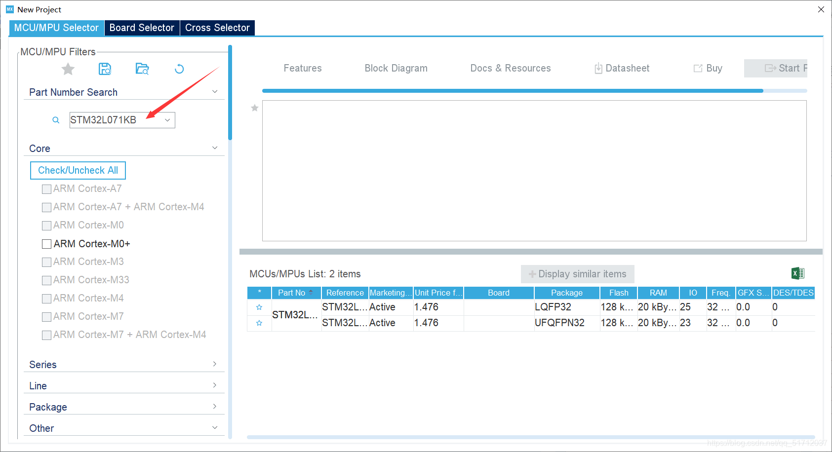
1.进入STM32CubeMX选择相应的开发板
2.将用于控制OLED的引脚设置为推免输出
PA8和PB4分别为OLED的SCL引脚和SDL引脚,PB5控制OLED的开启与关闭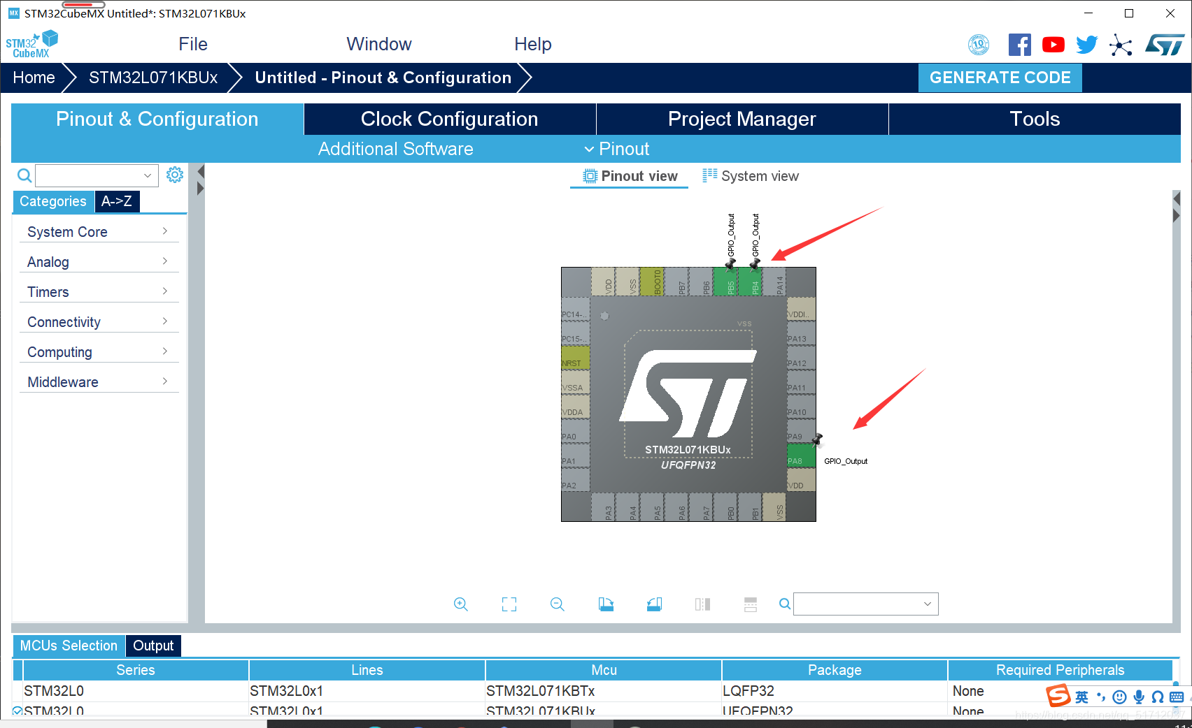
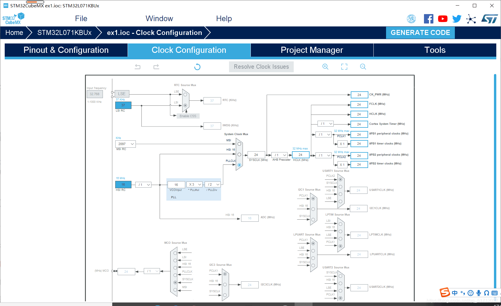
3.时钟配置选择
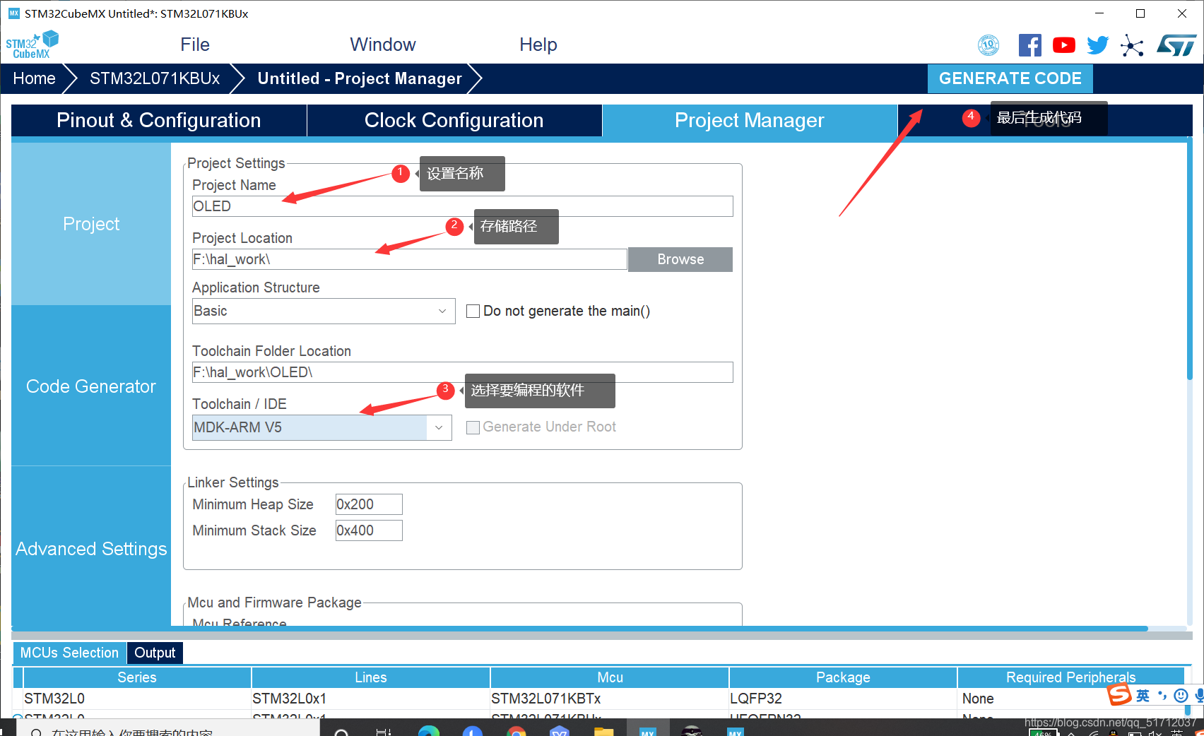
4.设置名称、选择路径及编程软件、生成代码
5.程序配置
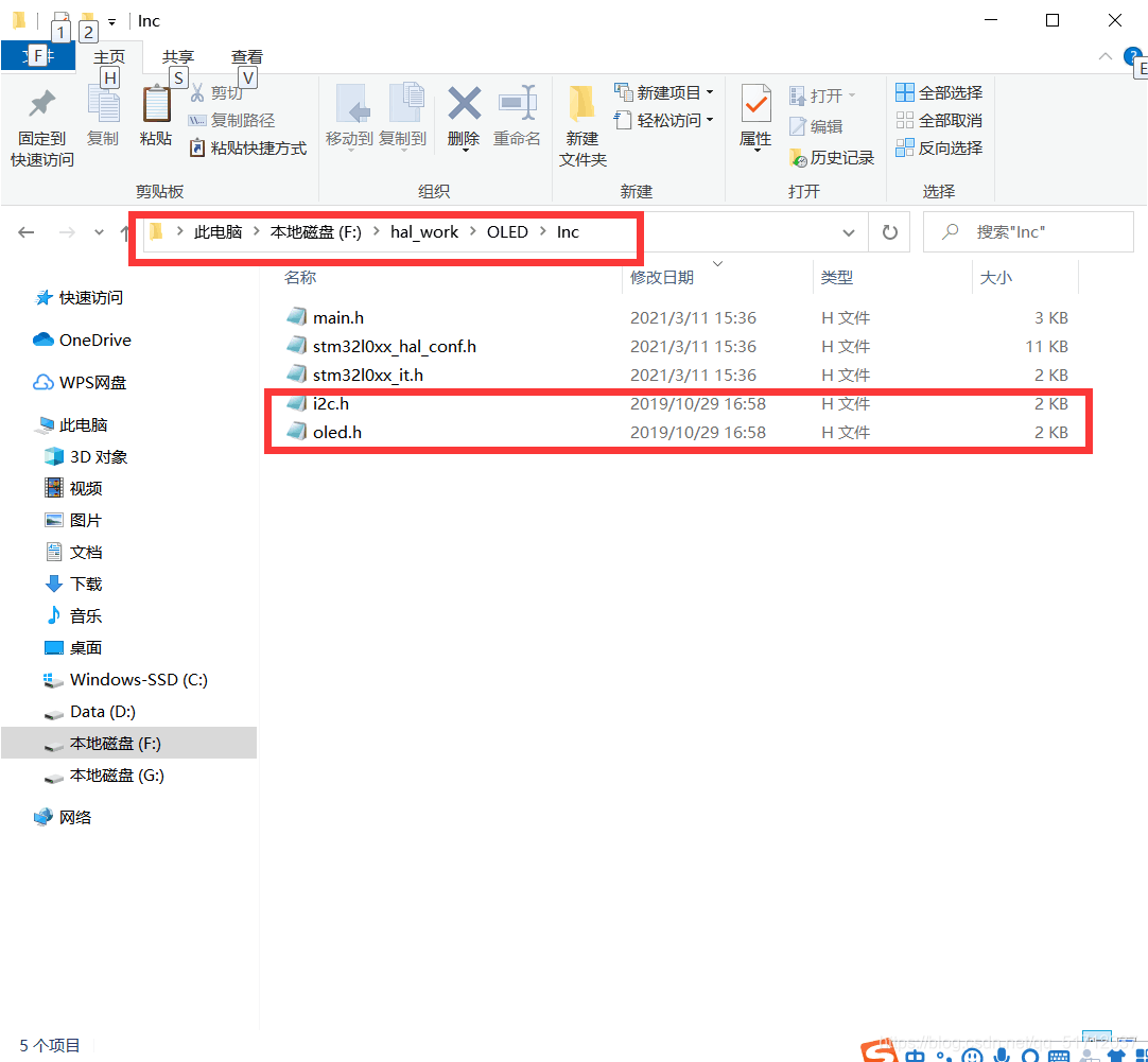
(1)添加底层驱动文件 (在程序路径下对应的Inc和Src文件夹下) 大赛会提供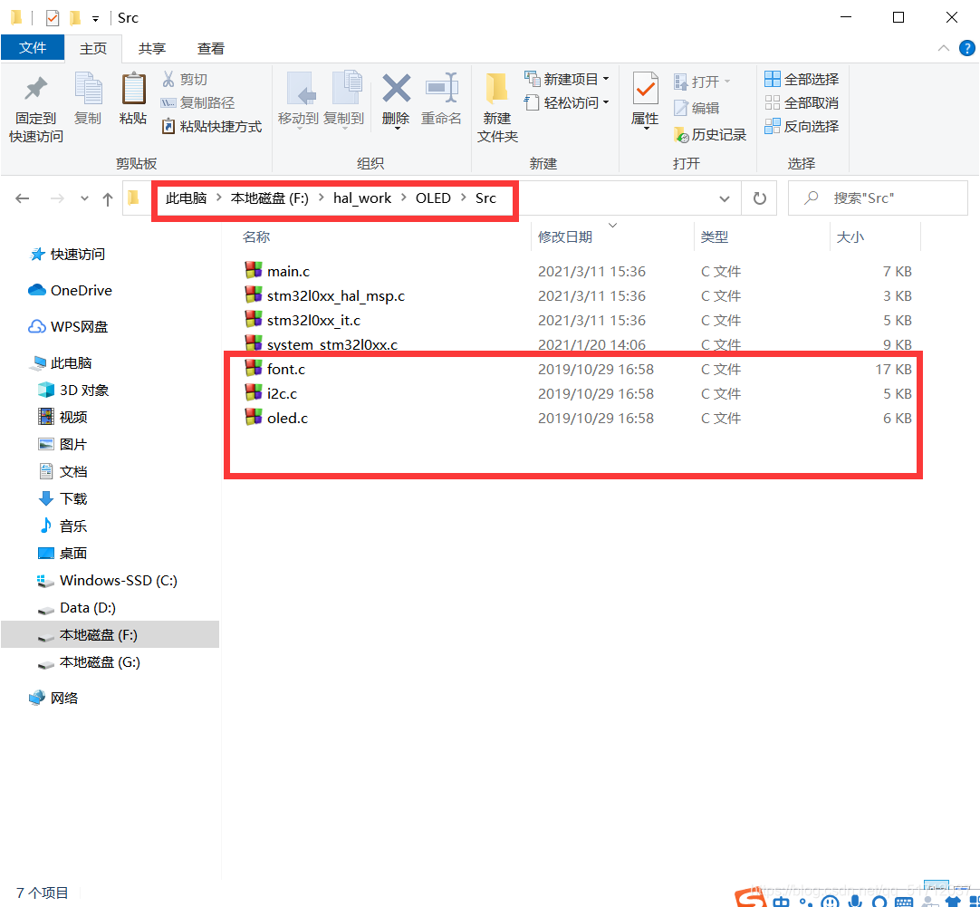
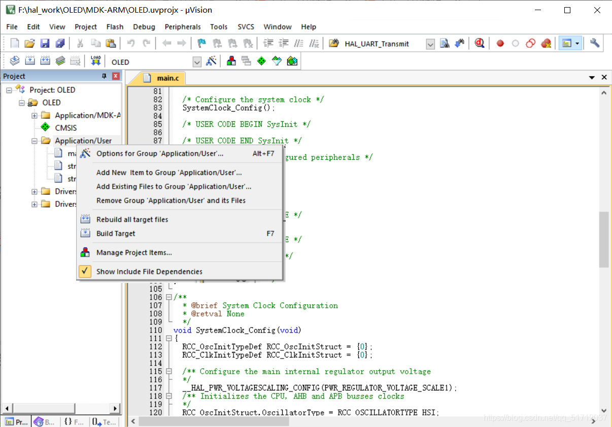
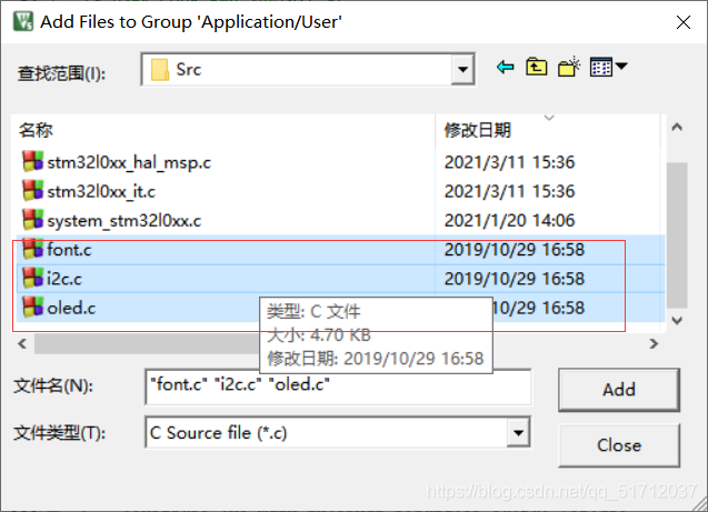
(2)在MDK5中添加这些驱动程序
6.程序补充代码
补充的代码主要是图下两个函数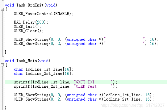
// main.c 补充的函数
/* Includes ------------------------------------------------------------------*/
#include "main.h"
#include "i2c.h"
#include "oled.h"
#include "stdio.h"
#include "stm32l0xx_hal.h"
#include "string.h"
/* Private includes ----------------------------------------------------------*/
/* USER CODE BEGIN Includes */
/* USER CODE END Includes */
void Task_BrdInit(void);
void Task_Main(void);
/* Private typedef -----------------------------------------------------------*/
/* USER CODE BEGIN PTD */
/* USER CODE END PTD */
/* Private define ------------------------------------------------------------*/
/* USER CODE BEGIN PD */
/* USER CODE END PD */
/* Private macro -------------------------------------------------------------*/
/* USER CODE BEGIN PM */
/* USER CODE END PM */
/* Private variables ---------------------------------------------------------*/
/* USER CODE BEGIN PV */
/* USER CODE END PV */
/* Private function prototypes -----------------------------------------------*/
void SystemClock_Config(void);
static void MX_GPIO_Init(void);
/* USER CODE BEGIN PFP */
/* USER CODE END PFP */
/* Private user code ---------------------------------------------------------*/
/* USER CODE BEGIN 0 */
/* USER CODE END 0 */
/**
* @brief The application entry point.
* @retval int
*/
int main(void)
{
/* USER CODE BEGIN 1 */
/* USER CODE END 1 */
/* MCU Configuration--------------------------------------------------------*/
/* Reset of all peripherals, Initializes the Flash interface and the Systick. */
HAL_Init();
/* USER CODE BEGIN Init */
/* USER CODE END Init */
/* Configure the system clock */
SystemClock_Config();
/* USER CODE BEGIN SysInit */
/* USER CODE END SysInit */
/* Initialize all configured peripherals */
MX_GPIO_Init();
/* USER CODE BEGIN 2 */
/* USER CODE END 2 */
Task_BrdInit();
/* Infinite loop */
/* USER CODE BEGIN WHILE */
while (1)
{
/* USER CODE END WHILE */
Task_Main();
/* USER CODE BEGIN 3 */
}
/* USER CODE END 3 */
}
void Task_BrdInit(void)
{
OLED_PowerControl(ENABLE);
HAL_Delay(200);
OLED_Init();
OLED_Clear();
OLED_ShowString(0, 0, (unsigned char *)" ", 16);
OLED_ShowString(0, 2, (unsigned char *)" ", 16);
}
void Task_Main(void)
{
char lcdLine_1st_line[16];
char lcdLine_2st_line[16];
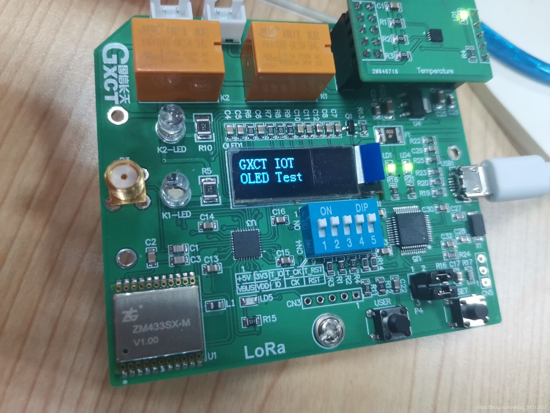
sprintf(lcdLine_1st_line, "GXCT IOT ");
sprintf(lcdLine_2st_line, "OLED Test ");
OLED_ShowString(0, 0, (unsigned char *)lcdLine_1st_line, 16);
OLED_ShowString(0, 2, (unsigned char *)lcdLine_2st_line, 16);
}
/**
* @brief System Clock Configuration
* @retval None
*/
void SystemClock_Config(void)
{
RCC_OscInitTypeDef RCC_OscInitStruct = {0};
RCC_ClkInitTypeDef RCC_ClkInitStruct = {0};
/** Configure the main internal regulator output voltage
*/
__HAL_PWR_VOLTAGESCALING_CONFIG(PWR_REGULATOR_VOLTAGE_SCALE1);
/** Initializes the CPU, AHB and APB busses clocks
*/
RCC_OscInitStruct.OscillatorType = RCC_OSCILLATORTYPE_HSI;
RCC_OscInitStruct.HSIState = RCC_HSI_ON;
RCC_OscInitStruct.HSICalibrationValue = RCC_HSICALIBRATION_DEFAULT;
RCC_OscInitStruct.PLL.PLLState = RCC_PLL_ON;
RCC_OscInitStruct.PLL.PLLSource = RCC_PLLSOURCE_HSI;
RCC_OscInitStruct.PLL.PLLMUL = RCC_PLLMUL_3;
RCC_OscInitStruct.PLL.PLLDIV = RCC_PLLDIV_2;
if (HAL_RCC_OscConfig(&RCC_OscInitStruct) != HAL_OK)
{
Error_Handler();
}
/** Initializes the CPU, AHB and APB busses clocks
*/
RCC_ClkInitStruct.ClockType = RCC_CLOCKTYPE_HCLK|RCC_CLOCKTYPE_SYSCLK
|RCC_CLOCKTYPE_PCLK1|RCC_CLOCKTYPE_PCLK2;
RCC_ClkInitStruct.SYSCLKSource = RCC_SYSCLKSOURCE_PLLCLK;
RCC_ClkInitStruct.AHBCLKDivider = RCC_SYSCLK_DIV1;
RCC_ClkInitStruct.APB1CLKDivider = RCC_HCLK_DIV1;
RCC_ClkInitStruct.APB2CLKDivider = RCC_HCLK_DIV1;
if (HAL_RCC_ClockConfig(&RCC_ClkInitStruct, FLASH_LATENCY_1) != HAL_OK)
{
Error_Handler();
}
}
/**
* @brief GPIO Initialization Function
* @param None
* @retval None
*/
static void MX_GPIO_Init(void)
{
GPIO_InitTypeDef GPIO_InitStruct = {0};
/* GPIO Ports Clock Enable */
__HAL_RCC_GPIOA_CLK_ENABLE();
__HAL_RCC_GPIOB_CLK_ENABLE();
/*Configure GPIO pin Output Level */
HAL_GPIO_WritePin(GPIOA, GPIO_PIN_8, GPIO_PIN_RESET);
/*Configure GPIO pin Output Level */
HAL_GPIO_WritePin(GPIOB, GPIO_PIN_4|GPIO_PIN_5, GPIO_PIN_RESET);
/*Configure GPIO pin : PA8 */
GPIO_InitStruct.Pin = GPIO_PIN_8;
GPIO_InitStruct.Mode = GPIO_MODE_OUTPUT_PP;
GPIO_InitStruct.Pull = GPIO_NOPULL;
GPIO_InitStruct.Speed = GPIO_SPEED_FREQ_LOW;
HAL_GPIO_Init(GPIOA, &GPIO_InitStruct);
/*Configure GPIO pins : PB4 PB5 */
GPIO_InitStruct.Pin = GPIO_PIN_4|GPIO_PIN_5;
GPIO_InitStruct.Mode = GPIO_MODE_OUTPUT_PP;
GPIO_InitStruct.Pull = GPIO_NOPULL;
GPIO_InitStruct.Speed = GPIO_SPEED_FREQ_LOW;
HAL_GPIO_Init(GPIOB, &GPIO_InitStruct);
}
/* USER CODE BEGIN 4 */
/* USER CODE END 4 */
/**
* @brief This function is executed in case of error occurrence.
* @retval None
*/
void Error_Handler(void)
{
/* USER CODE BEGIN Error_Handler_Debug */
/* User can add his own implementation to report the HAL error return state */
/* USER CODE END Error_Handler_Debug */
}
#ifdef USE_FULL_ASSERT
/**
* @brief Reports the name of the source file and the source line number
* where the assert_param error has occurred.
* @param file: pointer to the source file name
* @param line: assert_param error line source number
* @retval None
*/
void assert_failed(uint8_t *file, uint32_t line)
{
/* USER CODE BEGIN 6 */
/* User can add his own implementation to report the file name and line number,
tex: printf("Wrong parameters value: file %s on line %d\r\n", file, line) */
/* USER CODE END 6 */
}
#endif /* USE_FULL_ASSERT */
7.实验现象

宁波官方开源宣传和活动阵地,欢迎各位和我们共建开源生态体系!
更多推荐

 13
13 0
0- 0


 已为社区贡献1条内容

所有评论(0)